

 Visit Our Product Finder

May 17, 2021
IMA Systems Overview
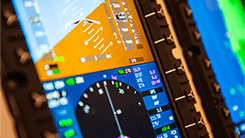
The latest generation of avionics systems are heavily based on the Integrated Modular Avionics (IMA) concept. Examples of aircraft that use IMA include the Boeing 787 & 777x, Airbus A380 & A350, F-35, and F-22 just to name a few. At the core of these IMA systems is a single integrated processing platform, which hosts multiple federated avionics applications. Utilizing a central processing platform provides uniform processor hardware and operating systems for the whole aircraft avionics system. This improves software reusability and simplifies system integration activities allowing for more efficient and rapid system development and upgrades over the life cycle of the program. It also increases the commonality of hardware components within the avionics system reducing the overall cost of maintaining the system.
IMA Architecture
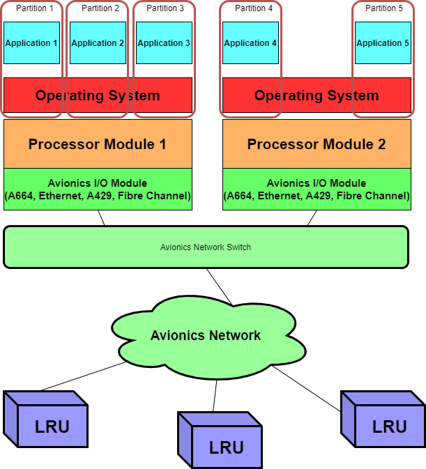
The avionics applications hosted on the IMA core processing system are typically time-critical and safety-critical real time applications. And because multiple application share the same processing hardware, the IMA system must provide a way to ensure that applications are partitioned such that a failure in one application cannot affect the health and operations of other applications sharing the common platform. Within an IMA system, a partition can be thought of as a container within which an application executes.
A partition enforces a set of constraints to ensure that applications can operate completely independently from each other on the same hardware. The memory used by an application partition is always protected. No applications are allowed (restricted by the OS) to access memory outside of their scope. Also, at any given time only one has access to the system resources.
There is NO competition for system resources, each partition is give a scheduled time window to access and utilize them. This means the each application (partition) is given a specific time window to execute on the shared processing resource. The scheduling of partitions is typically part of the IMA host operating system configuration and is organized using the common major and minor frame timing mechanism seen on MIL-STD-1553 buses and also on Telemetry downlinks.
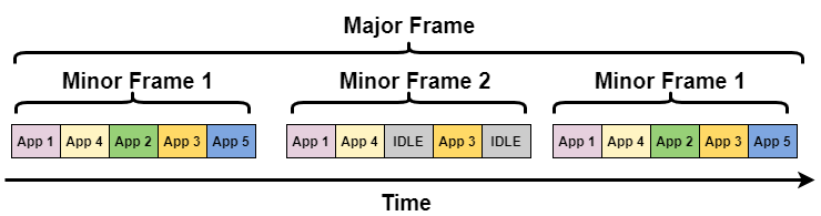
IMA Application (Partition) Scheduling
Each time an application is scheduled and active, it will generally read some data from the avionics network, process that data, and then transmit updated data. As a result of the scheduled and determinism of the application partitions the avionics messages on the network will also be transmitted and received in a regular and periodic manner consistent with the application’s partition scheduling within the IMA core processing system.
Test & Simulation of IMA Systems
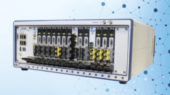
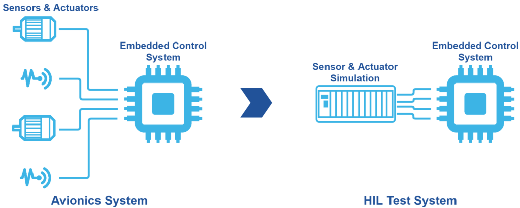
When designing, developing, and testing an avionics LRU or a hosted application for an IMA system, a typical test strategy is to use hardware-in-the-loop (HIL). With a HIL approach, a test system is used to simulate aircraft systems into the unit under test. This means that a test system must interface to the UUT via it’s connection to the avionics network, and the test system must simulate all of the relevant data messages and parameters of the avionics system. In typical, modern commercial or avionics systems, it has been estimated that there are greater than 70,000 data parameters. Therefore, to simulate the actual system, a high capacity, high performance test system is required.
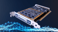
Simulating 1000’s of parameters in a test system, at a reasonable cost, requires high performance test instruments to interface to the avionics network. The instruments must be capable of off loading much of the avionics data simulation from the test system host CPU to avoid the need and complexity of a multi CPU test system. AIT’s new PXIe-25G instrument is an example of a high performance, high capacity instrument that fits the bill for such a test system. The PXIe-25G instrument provides 4 network interfaces. For each of the network interfaces the instrument is capable of simulating up to 16K periodic messages and for each message the period may be set in 1uS steps.
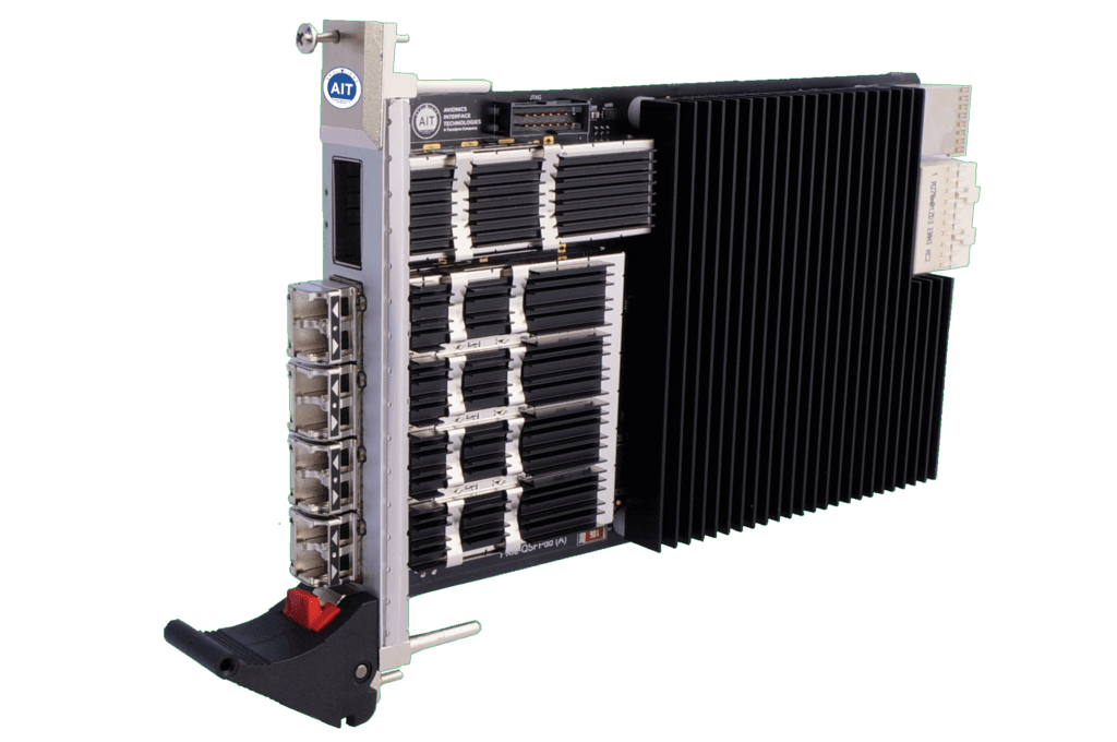
PXIe-25G – Fibre Channel, 10G/25G Ethernet Instrument
Why is such a high capacity, high capability Instrument needed?
You may ask, what’s the difference between the PXIe-25G and a relatively low cost Ethernet network interface card (NIC) typically used in a high capacity server and that are readily available from many suppliers?
First, the PXIe-25G is designed, from the beginning, to support Avionics test applications. It is user reconfigurable and supports multiple network types including 10G & 25G Ethernet, and Fibre Channel which are commonly used in the latest avionics aircraft (also coming soon! 40G & 100G Ethernet, and 100G InfiniBand .. Check back soon for more on this!).
Second, the PXIe-25G provides 4 network interfaces via Small Form Factor Pluggable (SFP) modules allowing easy switching between copper and optical network media.
Third, and probably most notably, the PXIe-25G not only provides upper layer protocol off-loading, it also offloads the simulation of application messages allowing a single instrument in an off the shelf, standard PXI Express system host a NON real-time OS to simulate up to 64K precisely timed periodic messages. Commercially available high speed NICs often provide some sort of upper layer protocol offloading relieving the host computer from processing protocol layers (such as TCP/IP) in the host OS software stack. The PXIe-25G not only offloads processing of the upper layer protocols, it ADDITIONALLY offloads the processing and scheduling of the periodic applications messages relieving the host processor of this load which is a necessity when required to simulate 1000’s of avionics messages.
Finally, the PXIe-25G instrument provides the ability to synchronize with external IRIG-B and IEEE-1588 master time clocks providing a range of possibilities such as precisely timing the transmission of data across multiple network interfaces and instruments and inserting precise time stamps into transmitted data.
Summary
Test and Simulation of high speed IMA systems requires high capacity test systems to simulate the 1000’s of aircraft parameters typical of an aircraft system, this is especially true in the latest systems using high speed networks based on Ethernet and Fibre Channel. To cost effectively simulate these systems, high capacity, reconfigurable instruments such as the AIT PXIe-25G instrument are required to provide key features including:
- Reconfigurable operations supporting Ethernet, Fibre Channel, and other network types
- Offloading of Upper Layer Protocols AND application message scheduling.
- Support for Copper AND Optical media
- Support of synchronization to external clocks and across instruments