- Overview: Avionics System Network Test
- HIL Avionics Test
- Avionics Network Switch Test
- ARINC-664/AFDX Avionics Systems Test
- Fibre Channel System Test
Comprehensive Avionics System Network Test Is Essential
Before an avionics system can be installed in an aircraft, designers and lab managers must verify exactly how it will operate under every conceivable condition that may occur during flight. There can be no surprises aloft.
System integration and test tools must be comprehensive but also straightforward to deploy in order to minimize test development and product verification time. All while guaranteeing full coverage of every potential fault condition.
AIT hardware and software products are the ideal solution for creating Hardware-in-Loop (HIL) simulation tests, as well as testing the switched networks such as ARINC-664/Ethernet and Fibre Channel variants that interconnect modern aircraft systems.
AIT’s Hardware-in-Loop Test Solutions.
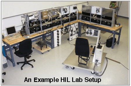 Whether used in a flight simulator or in real-time process systems such as simulating engine dynamics, successful HIL testing relies on AIT avionics hardware and tools including its unsurpassed variety of network interfaces.
HIL implementation software tools include drivers for LabVIEW RealTime, QNX, and Linux in addition to Windows.
AIT also provides Shared Memory products necessary to handle the enormous amounts of data requires for successful HIL system simulation and test.
Avionics Network Switch Testing
Older bus technologies such as MIL-STD-1553 and ARINC-429 are giving way to switched networks such as ARINC-664/Ethernet and Fibre Channel in newer avionics systems. These high bandwidth networks present sophisticated test challenges.
Avionics suppliers everywhere turn to AIT for ARINC-664/Ethernet and Fibre Channel test instruments as well as Network Simulator Systems.
System Test and Integration of ARINC-664/AFDX Avionics Systems
ARINC-664/Ethernet is employed in advanced aircraft, including Boeing 787, Airbus A380 and A350 as well as on several new military aircraft such as the KC-46.
A wide variety of AIT ARINC-664 products is used for verification and system integration testing power systems, engine controllers, and other avionics systems on these aircraft.
Click “Read More” for information about ARINC-664 testing.
System Test and Integration of Fibre Channel Avionics Systems
Fibre Channel is deployed on several new military aircraft programs including F-18, F-35, F-22 and is also used in cockpit display & video systems on several of the newer commercial aircraft.
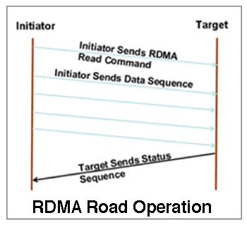
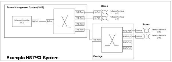
AIT supplies Fibre Channel interface products for testing upper layer protocols, including Asynchronous Subscriber Messaging (ASM), Remote Direct Memory Access (RDMA), as well as in weapons systems (HS1760) and ARINC-818 /FC-AV display systems.
More about AIT’s Practical Fibre Channel Test Tools.
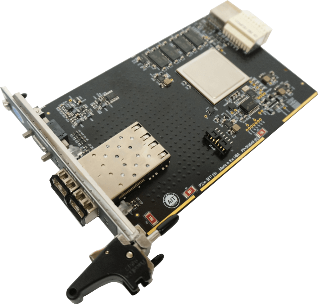
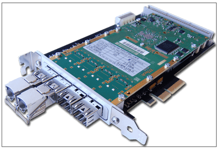
The AIT PCIe-FC4 test interface board and associated software, as well as other PCI, PCIe, PXIe boards from AIT, provide everything necessary to conduct comprehensive tests of Fibre Channel applications, ranging from simple End-System to demanding testing and verification of End Systems and/or switches.
AIT products may be used with the most popular avionics Upper Layer protocols including FC-AE-ASM, FC-AE-1553, FC-AE-RDMA and FC-AE-AV.
All AIT Fibre Channel modules employ multiple processors with large onboard RAM. An onboard processor runs the driver software, minimizing host CPU interaction, enabling autonomous operation with minimal interaction during time-critical applications.
Key Features
- Dual Port Data Generator operating at full line rates
- Dual Port Analyzer with nanosecond resolution
- IRIG-B Time Code Encoder/Decoder for synchronization
- Physical Bus Replay to reconstruct previously recorded data
- Live Data Capture to display FC data in real-time
- fcXplorerTest, Analysis, and Visualization Tool
- Data Corruptor™ for dynamically changing FC data on a link.
Application: Hardware-In-Loop [HIL] Avionics Test Solutions
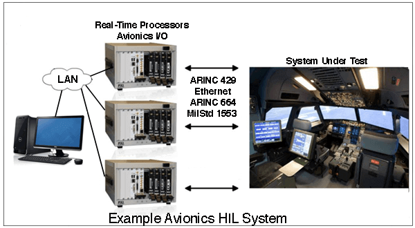 Hardware-in-Loop [HIL] tests avionics by simulating the dynamic environment in which the system will be operating.
HIL testing of avionics can range from a mockup of the cockpit such as a flight simulator. Or it can simulate environments such as engine or power system dynamics. Simulated data are fed to the system-under-test via the avionics bus, including ARINC-429 or MIL-STD-1553. Newer systems are connected via ARINC-664 or Fibre Channel.
A real time processor runs a mathematical model of the dynamics of the system-under-test and is connected to the control system via numerous analog and digital channels.
HIL Test Hardware
HIL systems are commonly based on multiple PXI- and PXI Express chassis running real time operating systems. Many are able to handle more than 70,000 aircraft parameters connected via thousands of analog and digital channels to the [avionics] system under test.
Shared/Reflective Memory

The enormous amount of data involved in HIL test of avionics systems requires a single bank of memory-shared multiple processing units [hosts].
Application: Network Switch Testing for ARINC-664/Ethernet and Fibre Channel
High speed data networks such as ARINC-664/Ethernet and Fibre Channel are the standard interconnection means in newer avionics systems.
 Ethernet data rates can range from 10Mbit/sec up to 10Gbit/sec. 1Gbit/sec Fibre Channel us common, but 2Gbit/sec and 4Gbit/sec data rates are on the near term horizon.
A single aircraft will typically include a mix of both copper and optical interfaces as well as multiple data link bit rates. This technology — often referred to as “switching fabrics”—leads to challenging functional testing requirements, especially when compared to simpler data buses such as ARINC-429 or MIL-STD-1553.
Both Ethernet and Fibre Channel test require tester capabilities that include:
- Both copper and optical interfaces
- Embedded data generation
- Adaptable Ethernet and Fibre Channel protocol cores
AIT supplies ARINC-664/Ethernet and Fibre Channel PXIe-based instruments that can support testing up to 30-port switches.
Ethernet Test Applications
Standard Ethernet (carrying UDP/IP) is sufficient for point-to-point applications where only two avionics devices are in communication, eliminating the need for a switch.
However, multiple devices and network points with real-time, deterministic requirements must use specialized Ethernet variants such as network path redundancy and partitioning for sharing of network bandwidth.
Avionics networks typically employ an avionics-specific protocol such as ARINC-664 or Time-Triggered Ethernet (TTE) that define special data frames and configurable data rates. In addition, the functional test system must be able to generate high data rates (up to 10Gbit/sec) on anywhere from 16 to 24 Ethernet interfaces.
Advanced aircraft such as B787, A380, and A330 use Ethernet-based avionics networks such as ARINC-664/AFDXTM™ and Time Triggered Ethernet (SAE AS6802)
![]() Explore more details of system test of ARINC-664/ AFDX™ Networks.
Explore more details of system test of ARINC-664/ AFDX™ Networks.
The ARINC-664 specification defines aircraft data networks that use Ethernet (IEEE 802.3) and upper layer protocols such as UDP, IP, and A653. Data rates for ARINC-664 networks range from 10Mbps to 1Gbps. Physical network interfaces may be copper or fiber optic.
Originally developed for the Airbus A380 program, many avionics systems now employ Full Duplex Switched (AFDX™) Ethernet. AFDX is used on other Airbus aircraft and has been adopted by other advanced aircraft programs, including Boeing 787 and military aircraft such as the KC-46.
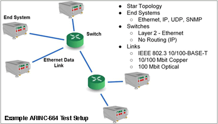 AIT’s ARINC-664 test hardware and software provide complete test and simulation of all network functions and interconnections. VL traffic shaping, redundancy management, and IP fragmentation and reassembly are all handled by the test system.
Key ARINC-664 Test System Features
- Supports IEEE 802.3 10/100/1000 Mbit/s Full‐Duplex Ethernet links
- Simulates multiple ARINC-664 End Systems, including VL traffic shaping and input VL redundancy management
- Supports up to 128 Output VLs and 512 Input VLs
- Supports up to 1024 Sampling & Queuing output message ports and up to 4096 input Sampling & Queuing message
- IRIG‐B Time Synchronization
- Provides network statistics including VL message counts and data rates
- Automatic message sequencing & periodic data generated onboard
- Includes Windows XP/7/8, Linux, VxWorks and LabVIEW Real Time Drivers and APIs
![]() Get more Information about AIT ARINC-664 test solutions
Get more Information about AIT ARINC-664 test solutions
Fibre Channel Test Applications
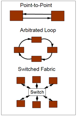 Originally arising out of the commercial Storage Area Network (SAN) market, Fibre Channel has been widely adopted to avionics applications. It can support point-to-point, star network, and ring network topologies using optical or electrical network interfaces.
The most common application of Fibre Channel point-to-point topology is ARINC-818-based system, which stream data from a video source to display devices. While this is not a switched fabric architecture, high video data rates require test equipment that can be configured for data rates from 5Gbit/sec to 30Gbit/sec.
Fibre Channel is employed in a variety of ways on several new military aircraft programs, including cockpit display systems and Asynchronous Subscriber Messaging (ASM) and Remote Direct Memory Access (RDMA) applications.
Fibre Channel also has been adopted for other applications, resulting in new avionics standards such as ARINC-818 specification for avionics displays as well as MIL-STD-1553 implemented over Fibre Channel as the HS1760 specification for military aircraft stores applications.
Fibre Channel System Integration and Test Requirements
Each of these protocols present substantial testing challenges. Given the high bit rates of a Fibre Channel network, traditional data logging approaches such as those used for MIL-STD-1553 simply don’t work.
For example, a Fibre Channel link operating at 1.065Gbps will generate 200Mbp, which would create just under 7 terabytes of data in an hour. A typical 24 port Fibre Channel switch would generate upwards of 168 terabytes of data in an hour.
Rather than simply data collection, a new test strategy and instrumentation needs to include the following:
- Both optical and copper interfaces must be supported
- Embedded on-board data generation is required to stimulate and measure the high data rates and real time response requirements.
- Ethernet and Fibre Channel protocol cores must be available in order to be able to modify commercial protocols for specific support of avionics adaptations.
AIT Provides Practical Fibre Channel Test Tools
The AIT PCIe-FC4 test interface board and associated software, as well as other PCI, PCIe, PXIe boards from AIT, provide everything necessary to conduct comprehensive tests of Fibre Channel applications, ranging from simple End-System to demanding testing and verification of End Systems and/or switches.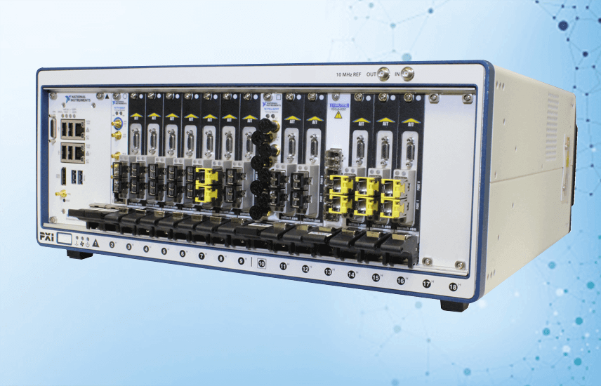
AIT products may be used with the most popular avionics Upper Layer protocols including FC-AE-ASM, FC-AE-1553, FC-AE-RDMA and FC-AE-AV.
All AIT Fibre Channel modules employ multiple processors with large onboard RAM. An onboard processor runs the driver software, minimizing host CPU interaction, enabling autonomous operation with minimal interaction during time-critical applications.
Key Features
- Dual Port Data Generator operating at full line rates
- Dual Port Analyzer with nanosecond resolution
- IRIG-B Time Code Encoder/Decoder for synchronization
- Physical Bus Replay to reconstruct previously recorded data
- Live Data Capture to display FC data in real-time
- fcXplorerTest, Analysis, and Visualization Tool
- Data Corruptor™ for dynamically changing FC data on a link
Network Data Simulation
For both Ethernet and Fibre Channel switched network testing, a real-time network simulation system is a far more efficient and cost effective solution than attempting to create a customized network to create such complex test data.
![]() Explore AIT Network Simulator Systems
Explore AIT Network Simulator Systems
Application: System Test and Integration of ARINC-664/AFDX Avionics Systems
The ARINC-664 specification defines aircraft data networks that use Ethernet (IEEE 802.3) and upper layer protocols such as UDP, IP, and A653. Data rates for ARINC-664 networks range from 10Mbps to 1Gbps. Physical network interfaces may be copper or fiber optic.
Originally developed for the Airbus A380 program, many avionics systems now employ Full Duplex Switched (AFDX™) Ethernet. AFDX is used on other Airbus aircraft and has been adopted by other advanced aircraft programs, including Boeing 787 and military aircraft such as the KC-46.
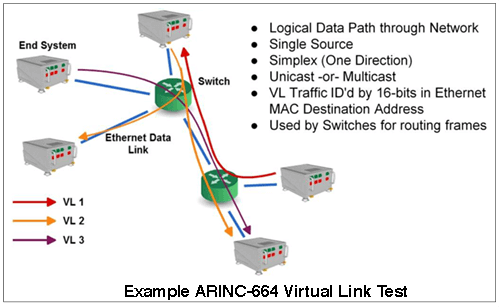 AIT’s ARINC-664 test hardware and software provide complete test and simulation of all network functions and interconnections. VL traffic shaping, redundancy management, and IP fragmentation and reassembly are all handled by the test system.
Key ARINC-664 Test System Features
- Supports IEEE 802.3 10/100/1000 Mbit/s Full‐Duplex Ethernet links
- Simulates multiple ARINC-664 End Systems, including VL traffic shaping and input VL redundancy management
- Supports up to 128 Output VLs and 512 Input VLs
- Supports up to 1024 Sampling & Queuing output message ports and up to 4096 input Sampling & Queuing message
- IRIG‐B Time Synchronization
- Provides network statistics including VL message counts and data rates
- Automatic message sequencing & periodic data generated onboard
- Includes Windows XP/7/8, Linux, VxWorks and LabVIEW Real Time Drivers and APIs
Application: Fibre Channel System Integration and Test
Fibre Channel Overview
Growing numbers of military and commercial aircraft programs have adopted a Fibre Channel avionics communication architecture. Since it is a deterministic system[1], it provides highly reliable data transfer between devices using several different Upper Layer Protocols (ULP).
There are three popular applications of Fibre Channel in recent avionics and video systems.
1. FC-ASM and FC-RDMA Upper Layer Protocols
Anonymous Subscriber Messaging (ASM) protocol used on the F-35, and Remote Direct Memory Access (RDMA), used on the F-18.
Learn more about testing upper layer protocols such as ASM and RDMA.
2. MIL-STD-1553 Mapped to Fibre Channel
MIL-STD-1553 (implemented in Fibre Channel as FC-AE-1553), used for weapons systems implemented using MIL-STD-HS1760
3. ARINC-818 Avionics Digital Video Bus (ADVB)
ARINC-818 is an industry standard that defines a digital video interface link and protocol used for high-speed digital video display data communications.
The ARINC-818 protocol is being adopted widely for display systems and is the bus connecting mission and video processors to a variety of displays. High-resolution radars and IR and optical sensors also use ARINC-818.






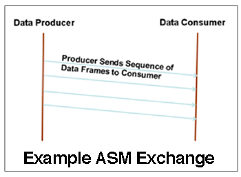 ASM is used for avionics applications designed to be run at periodic rates where both source and recipient of the data are anonymous. Nor does ASM require a master controller. Its most notable use is on F-35 avionics systems.